Efficiency & Emission Systems
Design Basis
Lotus Energy Group implements a selective catalytic reduction (SCR) system to reduce NOx emissions by 90% reduction and CO emissions by 93% reduction for diesel fired turbines. The SCR has been proven to be an excellent application for emission reduction. Lotus design team experienced and evaluated alternative approaches for NOx reductions, and are confident that SCR’s technology is the most efficient and trouble-free solution available. This solution ensures that the reduction of NOx in the stack does not impede combustion or turbine operation, nor is flame stability, load response, and turndown compromised. Ammonia flow rate is controlled based on a feed forward signal from your turbine’s fuel flow transmitter and the predetermined uncontrolled NOx emissions. Precise control of ammonia flow vs. NOx is obtained throughout the entire turndown range to minimize NOx and ammonia slip. Ammonia vapor from the Ammonia Flow Control Unit (AFCU) is diluted with air before entering the Ammonia Injection Grid (AIG) located upstream of the SCR Catalyst.
SCR NOx and CO Catalyst
The NOx catalysts and CO catalysts feature:
• High removal activity
• Low pressure drop
• Low SO2 oxidation rate
• Excellent durability
NOx and CO catalysts are based on a corrugated, fiber reinforced titanium dioxide (TiO2) carrier. The carrier is impregnated with the active components: vanadium pentoxide (V2O5) and tungsten trioxide (WO3). The catalyst is shaped to a monolithic structure with a large number of parallel channels. DNO catalysts are based on a fibre reinforced noble metal-tungstein-titania catalyst with various vanadium levels to balance the acitivity, the SO2 oxidation and the thermostability. The catalyst is available with a 0.4 mm wall. The unique catalyst design provides a highly porous structure with a large surface area and an ensuing large number of active sites. The high and well-defined porosity is the key to:
• A high NOx removal level with minimum ammonia slip
• A high CO removal level with high selectivity of ammonia oxidation towards nitrogen
• A low activity towards SO2 oxidation, minimizing the risk of fouling downstream equipment
• A high poison resistance ensuring a long and stable service life
• A substantially lower weight than for conventional plate or extruded catalysts, allowing a fast
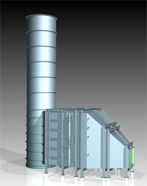
Catalyst Reactor and AIG Housings
Steel reactor housings with internal grid and structural supports will be provided to mount the catalyst modules and AIG in. The housings will be internally lined with 4” 8# ceramic fiber insulation and covered with 14 GA Cor-Ten sheeting. The CO catalyst will be installed immediately upstream of the AIG and the NOx catalyst will be installed approximately 10’ downstream of the AIG.
Ammonia Flow Control Unit (AFCU)
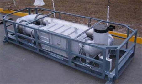
Ammonia flow control components for pure anhydrous ammonia (99.9%) is skid mounted in a compact space-saving arrangement where all operating devices are within close proximity of each other and within easy access for the operator. The AFCU skid consists of an all stainless steel piping manifold with safety valve, pressure switches, pressure reducing regulator, mass flow pneumatic control valve with electric heat tape, insulation, and aluminum lagging. The skid includes a stainless steel NEMA 4 control panel with alarm bell, on/off switches, indicating lights and PID loop controller with Plexiglas cover. Two (2) regenerative style dilution air blowers are included (one as redundant back-up).
The Ammonia Injection Grid (AIG)
consists of a stainless steel header feeding a group of stainless steel injection lances distributed across the flue gas duct. The AIG provides uniform injection of the ammonia/air mixture over the duct cross section. The AIG is mounted in a carbon steel duct with interior insulation and Cor-Ten liner. The AIG to be field installed 10’ upstream of the catalyst reactor housing.